|
One of the more common questions I get from
gents finishing an XL250/350 top-end repair is "how
do I mount the &@#!)$ cam sprocket".
With a new (or good) cam chain tensioner,
with a distinct "bow" to it, and even with loosening
the cam chain tensioner adjustment bolt, getting the cam
sprocket to slip onto the cam can be a chore.
Some time back, can't remember just when, I
tired of fighting this procedure and built a jig (this is an
actual picture, but not actual size.)
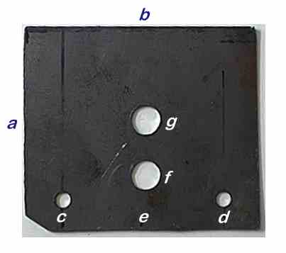
The jig was cut from sheet metal with the
overall dimensions of:
a = 3-1/2" and b = 3-7/8".
It mounts on the left side of the engine,
where the point's plate sits, using mounting holes
"c" and "d" and the same Phillips head
machine screws used to mount the point's plate.
To perform this procedure, before mounting
the jig to the engine, pull up on the cam chain, position the
end of the cam (lobes down) thru the hole in the cam sprocket
(index lines horizontal), then mount the cam chain around the
cam sprocket. The sprocket will now be sitting loose on the
shaft end of the cam.
Position the cam in the journals, then
mount the jig, with the end of the cam through hole
"f".
Now, insert a flat-blade screw driver thru
hole "g" and catch just the inside lip of the cam
sprocket hole with the very end of the blade.
GENTLY, pry the cam sprocket onto the
cam/sprocket surface.
Finally, making sure that the engine is at
top-dead-center ("T" on the flywheel), position the
cam lobes "down", making sure the horizontal
marks (180 degrees apart, scribed on the sprocket) are in-line
with the horizontal mating surface of the cam cover.
Secure the sprocket to the cam with the two
bolts. Rotate the flywheel and check for proper alignment.
If the flywheel mark is at the
"T", and the cam lobes are pointing up, your
assembly has just resulted in the most common engine builder's
mistake, the cam timing is 180 degrees out of phase. Been
there - done that, got the "dunce cap" T-shirt.
The other dimensions are
c to d = 2-3/4"
c to e = 1-3/8"
f to horizontal line drawn between c and d = 3/8"
f to g = 15/16"
home dimensions are
c and d = 1/4"
f and g = 1/2".
As I mostly build XL350 engines, I don't
know if the jig will serve for all other XLs, but I do know it
also works on a XL250 side port unit.
If you make a similar jig for a different
engine then please e-mail me with the dimensions; and, let me
know your experiences.
|